Jeremy W. Langston

Personal Website

Portable Console Emulator using a Raspberry Pi

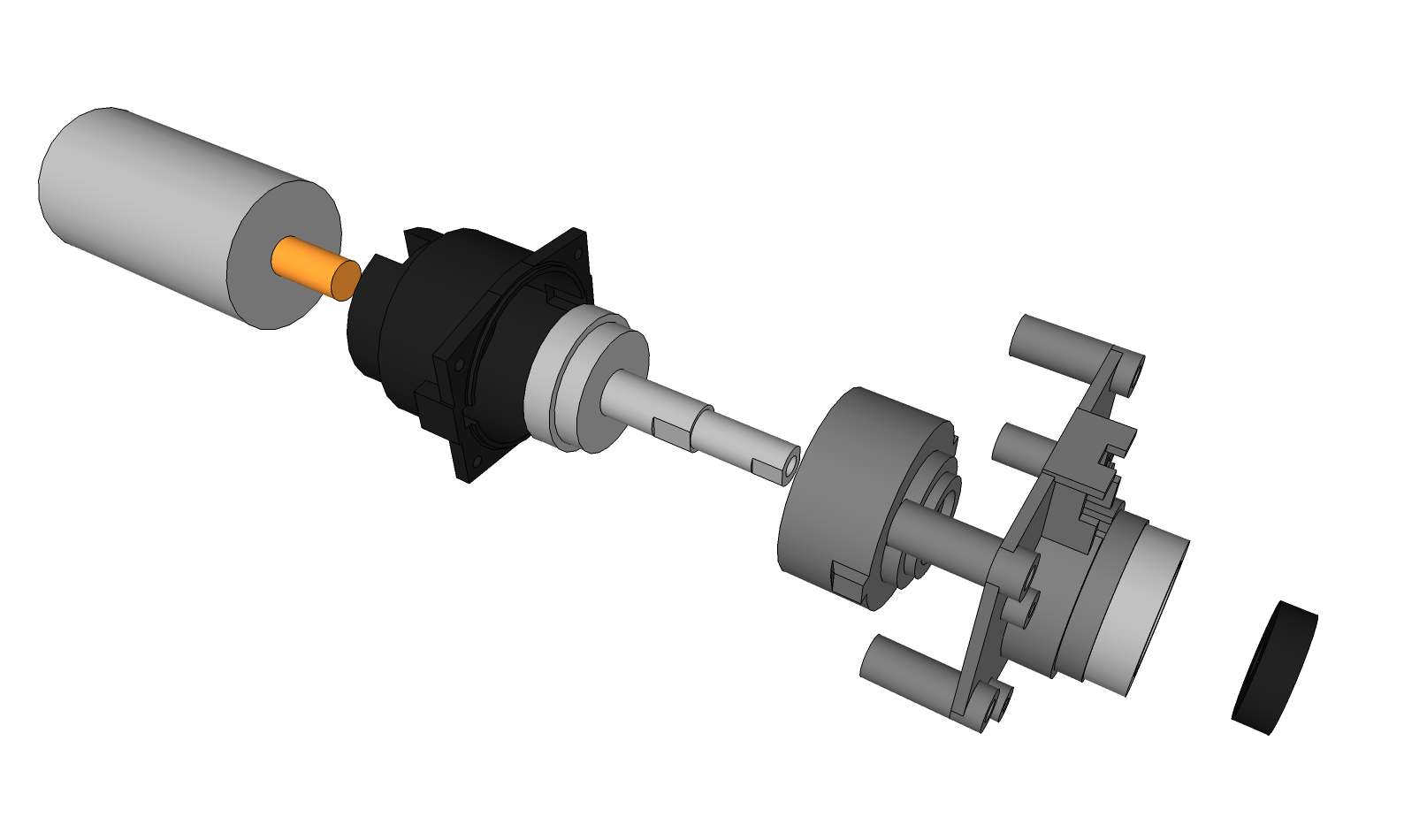
Here’s a couple pictures from my last project:  tablet-based teleprompter with 15mm support rods and a quick disconnect camera system.  It turned out very well.  One of these days I’ll post up some more detail.

image image


But that project’s over and my shop is missing me.  This time I’m getting back to electronics.  Lately I’ve been playing the old NES games.  Well, when I say playing, I mean with my original NES.  I left a cartridge in the console the last time I played it and all of the pins got stressed, resulting in the blinking display.  This is typical when the pins connecting to the cartridge don’t make a good connection.  Bending them back was an easy fix, and didn’t even require the removal of the security chip.

Anyways, now I’m trying to make a portable system based on a Raspberry Pi.  Having installed the RetroPie distribution, running NES/SNES/Genesis/etc. emulators are a breeze.  I bought a few other components to make sure everything would work, and then started designing.

Portable Console v3 - 1Portable Console v3 - 2

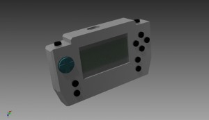
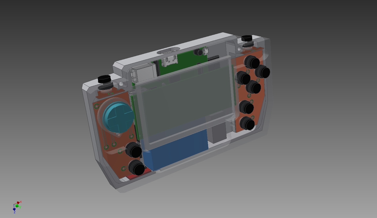
Here’s what I’ve come up with.  I went through several revisions, trying to maximize space and portability.  At the same time, I tried to keep ergonomics in mind.  The size is a bit chunky, but feels good in the hand so far.  The enclosure is made of two pieces of polypropylene.  Originally I wanted it all milled out of solid aluminum.  Not wanting to spend 500 hrs making billions of passes milling, I chickened out for something much easier to machine (set RPMs low and make heavy cuts).

The parts I’m using are, mostly, shown below:  a Raspberry Pi, a 12V-5V switching regulator from eBay, a 4.3″ TFT car monitor from Amazon, a 12V LiPo battery with integrated charging and power switch components from eBay, and the little silicon pads from a Logitech Gravis Gamepad Pro that doesn’t work.  Oh, and a Teensy v3 to make the gamepad portion.

image


Since I’m splitting up the buttons from a traditional gamepad with the monitor in the middle, I needed some custom PCBs.  Gamepads work by closing circuits to ground via silicon pads with bits of carbon in it.  I could use some pushbuttons, but wanted to retain the nice action of a gamepad button.  Once I got the dimensions and button positions from Inventor, I made the PCB layout in DipTrace.  Then I used the tried and true laser toner, copper clad PC board, and ferric chloride PCB solution.  It took a few tries, but I like the results.

image  image

The 4.3″ TFT monitor is a great deal for $18.  I just need to make some changes to get it how I wanted.  First was to remove the case and hardwire the power to the battery and to the regulator.  Next I needed to remove the pushbuttons on the back of the monitor.  Eventually I’d like to control them via my Teensy microcontroller because they bring up the menu for setting things like brightness, etc.

image  image

When I first got the regulator I was a bit suspicious since it looked like there was a big glob of solder bridging a couple nodes.  Metering it all out it appears OK.

image  image


I then hardwired power and NTSC video directly to the Raspberry Pi.  The main regulator pads were the best place to supply 5V and bypass the USB port.

image  image

Lastly I started fabricating the front of the enclosure.  I’ve got about 8 hrs into it now and haven’t made any mistakes – yay!  Unfortunately I ran out of polypropylene and had to put in a new order.  In the meantime, I am going to make the buttons.  Well, that’s all for now…


PDAnet and Internet Connection Sharing without DHCP – Step by Step

I recently wanted to share my Android phone’s internet connection to two Windows computers.  After some doing, here is the solution (naming might differ on different versions of Windows, I’m using XP):

  1. Download and install PDAnet for your Android phone and on one of the Windows computers, referred to as Computer1.
  2. Once installed, follow the directions for connecting Computer1 to the internet.  PDAnet includes these instructions, but basically you turn on the PDAnet app on the phone and click “Turn on PDAnet” or something like that.  (You also need to have USB debugging enabled, see instructions.)  You need to install the software on Computer1 before you connect to your phone via USB.  If your phone prompts you with four choices, such as Charge, USB Mass Storage, etc., select Charge.
  3. Now in the system tray on Computer1, right-click the PDAnet icon and select “Connect”.  After this, Computer1 should have internet access.
  4. Next connect Computer1 and Computer2 with an ethernet cable.  Older network adapters require a cross-over cable.
  5. On Computer1, go to the properties of the ethernet connection (e.g. “Local Area Connection” -> r-click -> “Properties”).  Double-click “Internet Protocol (TCP/IP)”.  Set the IP address to “192.168.0.1” and subnet mask to “255.255.255.0” and click “Ok” out of all of that.
  6. On Computer1, go to the properties of the PdaNet Modem.  Click the “Advanced” tab.  I disabled my firewall to make things easy.  Click the box “Allow other network users to connect through this computer’s Internet connection”.  In the drop-down box, select the ethernet connection you configured in Step 5.  Unselect the other two boxes.  Click “Ok”.
  7. Still on Computer1, click “Start”->”Run” (or hold the Windows keyboard button and press “R” at the same time).  In the box, type “cmd” and press “Ok”.  In the black command window type “ipconfig /all”.  Look for the PdaNet connection “PPP adapter for PdaNet Modem”.  Under that should be “DNS Servers . . . . “.  Write down that number, as it will be used on Computer2.
  8. On Computer2, set up the ethernet connection using the same procedure as in Step 5, except use the IP address “192.168.0.2” and for the Default Gateway put “192.168.0.1”.  While you are there, click “Use the following DNS server addresses” and put the number you wrote down in Step 7 under “Preferred DNS server”.
  9. You should have internet access on both computers now!

If you are having problems, try this:  back on Computer1, type “ping 192.168.0.2”.  If it says “Reply from 192.168.0.2…” then you are most of the way there.  Otherwise go back and check the steps.  Type “ping 74.125.229.16” to see if you can access Google without DNS name resolution.  If it doesn’t reply, then PDAnet isn’t connected or a step was skipped.  Finally type “ping www.google.com” to see if the DNS configuration is correct.  If it doesn’t reply, then look at the settings seen in Steps 7 and 8.

Sawbot Update 3 – Rough, RUFF Drawings

Here’s a quick mock-up of what I’m planning for Sawbot.

The general idea is a 4WD independent differential-drive with a central pivot between the left and right sides providing suspension.  Each wheel is individually driven using its own motor and ESC.  Doing this allows for more functionality in turning, and slip monitoring when coupled with an ammeter or an encoder.  The central pivot point will be a passage for wiring, etc.  You can see the arduino for scale, as the tire OD is 6″.  Large.  Not sure what will change or will stay the same.  With my Sketchup track record, I’ll likely never see this platform…

Sawbot Update 2

So, I wrote a bit of code to control brushed DC motors from a Logitech USB Gamepad -> Custom VC++ Software -> Custom Arduino Software -> Motor Driver -> Brushed DC motor.  This is mostly just temporary code to test things.  Ultimately there will be three modes of operation:   remote via RC transmitter, remote via PC, and autonomous.  Depending on how I decide to control this thing, the RC transmitter/receiver will be pretty much plug-n-play.  Autonomous control will come much later.  This is something I’ve done before and know how much work goes into it.  Remote via PC is fairly straight-forward, as I mentioned.

Here’s my code, including the Arduino sketch and the code for VC++:

DCMotor

The DCMotor class talks with the Arduino via the USB using RS232 communications.  I had to make my own protocol for passing commands to the Arduino to control the motors.  Right now each message is composed of the following:

<STX> <Forward> <Speed[7-0]> <Speed[15-8]><Speed[23-16]><Speed[31-24]> <ETX>

Each are bytes, where:

STX = start of text = 0x02

Forward = 1-forward, 0-back

Speed[#-#] = individual bytes of the unsigned int speed

ETX = end of text = 0x03

Inside the DCMotor zip are the DCMotorTestDlg .cpp/.h files I’ve used.  They can’t be directly built because there are several other files needed.  Really all you need to know are how to use the DCMotor class and how to talk to gamepads.  In the OnInitDialog() method of DCMotorTestDlg I make the following three calls:

m_DCMotor.Create(“DC Motor”, WS_CHILD|SS_NOTIFY, CRect(0,0,0,0), this, 6666);

m_DCMotor.Open(“COM13”);

SetTimer(m_pTimer, 20, NULL);

Create() is used for making a window.  The window is used for sending messages internally and externally. Internal messages go to/from the internal thread which does the communications to the Arduino.  External messages aren’t really used for much right now, but I’ll eventually rewrite all of this to be a Sawbot controller which will give status updates.  Open() does exactly what you think.  For now, I’m running at 9600, 8, n, 1.  SetTimer() is used for polling the gamepad for button presses.  I won’t get into the details of why I do polling instead of interrupts, except to say that polling allows for more use of the gamepad.  Feel free to let me know I’m wrong.

As you will see in OnTimer() method of DCMotorTestDlg, I issue move commands to the DCMotor class based on the analog X position of the gamepad.  Sorry about the massive lack of commenting.  I wrote it fast, but what isn’t obvious can be Google’d.  Just in case, here’s a quick explanation of what I’m doing.
if (bJoyPresent){
if ((joyInfoEx.dwXpos < 28672) || (joyInfoEx.dwXpos > 36864)){
if (joyInfoEx.dwXpos > 32767)
m_DCMotor.IssueCommand(true, (joyInfoEx.dwXpos – 32768)/128);
else
m_DCMotor.IssueCommand(false, (32767 – joyInfoEx.dwXpos)/128);
}
else {
m_nLastXpos = 32768;
m_DCMotor.IssueCommand(false, 0);
}
}

First, I’ve retrieved the gamepad/joystick info (refer to lines 104-109 of DCMotorTestDlg.cpp, not shown here).  If a gamepad is connected, then I check to see if I should command the motor to move.  I’ve put a dead-zone of 8192 (between 28672 and 36864).  This is to prevent the motor from always wanting to turn unless the value is exactly 32767.  Then I noticed a mistake.

The Arduino is an 8-bit microcontroller, and the pseudo-analog (read:  PWM) output I use to control the DC motor is 8-bit.  That’s a range of 0-255.  Much less than 0-32767.  So I divide by 128 to get in the appropriate range.  Not a big deal though as I doubt I will ever need to do anything more refined.

If you don’t quite follow my mental defection logic, feel free to leave a comment and I’ll explain.  Also, this code is very very basic and unfinished.  The Arduino code is easy to follow and uses the same protocol I stated above.  I’ll post up a demo when I get a chance.

Sawbot Update 1

I spent some time the other day modeling the HF 18V Circular Saw motor and bracket.  Since I don’t have the money for pro CAD programs, I use Google Sketchup.  Great product for free, and it’s very simple to use.  The most time I spend modeling is just using the calipers, rechecking, and then checking again.  I’ve posted the sketch to the Sketchup Warehouse.

HF 18V Circular Saw Motor

While modeling it, I’ve been thinking about how to mount it.  There aren’t any easy flat faces and the cast aluminum is only about 0.1″ thick.  Several options are available.  I could mill the front face flush and machine an aluminum mounting plate for it to mount to.  This isn’t my preferred choice because it could easily break and I’d be hosed.  Another option is to make a similar mounting plate without milling the current bracket.  That’s the easiest way out, and I haven’t completely decided against it.  The four deep holes on the corners could be threaded or just put a bolt and nut to it.  Since there isn’t a lot of material there, helicoils wouldn’t be an option, but there’s a full inch to bite onto so…I don’t know yet.

Another option is to make a custom bracket that would mate directly with the black plastic gear casing.  The longer I look at it, the easier it looks to do.  Here’s a closer look at what is actually inside.

As you can see, the current bracket houses a 6000RS series ball bearing.  I’m sure it’s there to stay, so I’d have to buy another if I remade it.  Over the next few days I will update my model to show these parts.  If you were wondering what the oddly shaped part was that rides on the shaft, it’s a locking mechanism for holding the shaft when you are changing blades on the saw.  Here’s the product manual showing an exploded parts list.

Edit:

I’ve redrawn the motor, bracket, and other inside goodness, and posted it to the Sketchup Warehouse.  The planetary gears aren’t drawn because I’m lazy.  Here’s an exploded view:

HF 18V Circular Saw Motor - Modeled Exploded View

« Older posts

© 2024 Jeremy W. Langston

Theme by Anders NorenUp ↑