Here’s a couple pictures from my last project: tablet-based teleprompter with 15mm support rods and a quick disconnect camera system. It turned out very well. One of these days I’ll post up some more detail.


But that project’s over and my shop is missing me. This time I’m getting back to electronics. Lately I’ve been playing the old NES games. Well, when I say playing, I mean with my original NES. I left a cartridge in the console the last time I played it and all of the pins got stressed, resulting in the blinking display. This is typical when the pins connecting to the cartridge don’t make a good connection. Bending them back was an easy fix, and didn’t even require the removal of the security chip.
Anyways, now I’m trying to make a portable system based on a Raspberry Pi. Having installed the RetroPie distribution, running NES/SNES/Genesis/etc. emulators are a breeze. I bought a few other components to make sure everything would work, and then started designing.
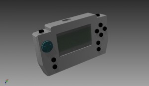
Here’s what I’ve come up with. I went through several revisions, trying to maximize space and portability. At the same time, I tried to keep ergonomics in mind. The size is a bit chunky, but feels good in the hand so far. The enclosure is made of two pieces of polypropylene. Originally I wanted it all milled out of solid aluminum. Not wanting to spend 500 hrs making billions of passes milling, I chickened out for something much easier to machine (set RPMs low and make heavy cuts).
The parts I’m using are, mostly, shown below: a Raspberry Pi, a 12V-5V switching regulator from eBay, a 4.3″ TFT car monitor from Amazon, a 12V LiPo battery with integrated charging and power switch components from eBay, and the little silicon pads from a Logitech Gravis Gamepad Pro that doesn’t work. Oh, and a Teensy v3 to make the gamepad portion.

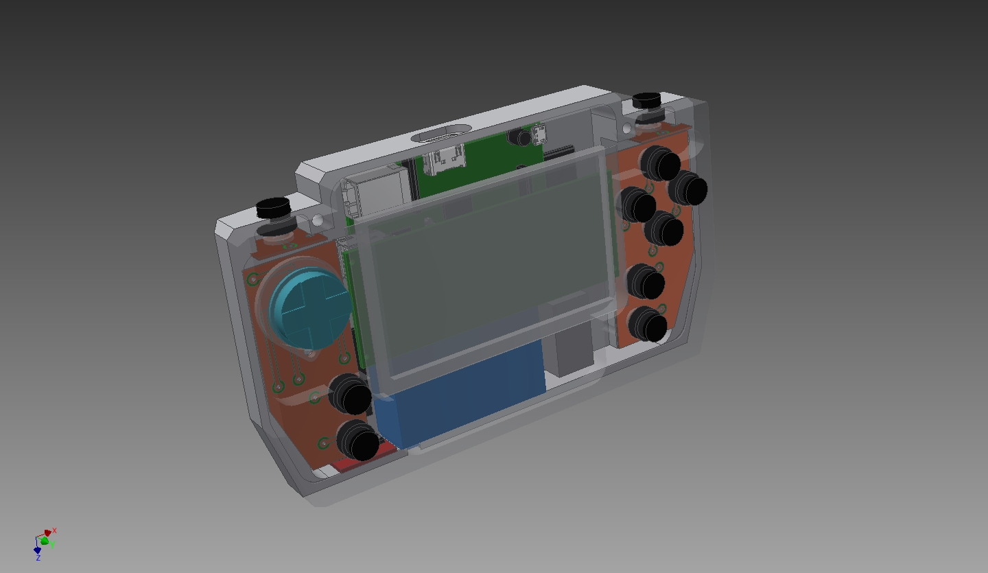
Since I’m splitting up the buttons from a traditional gamepad with the monitor in the middle, I needed some custom PCBs. Gamepads work by closing circuits to ground via silicon pads with bits of carbon in it. I could use some pushbuttons, but wanted to retain the nice action of a gamepad button. Once I got the dimensions and button positions from Inventor, I made the PCB layout in DipTrace. Then I used the tried and true laser toner, copper clad PC board, and ferric chloride PCB solution. It took a few tries, but I like the results.


The 4.3″ TFT monitor is a great deal for $18. I just need to make some changes to get it how I wanted. First was to remove the case and hardwire the power to the battery and to the regulator. Next I needed to remove the pushbuttons on the back of the monitor. Eventually I’d like to control them via my Teensy microcontroller because they bring up the menu for setting things like brightness, etc.


When I first got the regulator I was a bit suspicious since it looked like there was a big glob of solder bridging a couple nodes. Metering it all out it appears OK.


I then hardwired power and NTSC video directly to the Raspberry Pi. The main regulator pads were the best place to supply 5V and bypass the USB port.


Lastly I started fabricating the front of the enclosure. I’ve got about 8 hrs into it now and haven’t made any mistakes – yay! Unfortunately I ran out of polypropylene and had to put in a new order. In the meantime, I am going to make the buttons. Well, that’s all for now…
August 16, 2024 at 11:00 am
thanks
August 17, 2024 at 12:21 am
“I appreciate the easy-to-navigate structure and the quality of the content. Well done!”
August 19, 2024 at 1:25 am
شرکت
اعتماد شبکه پرهام
ارائه دهنده خدمات و تجهیزات پسیو و اکتیو شبکه
بیش از 10 سال سابقه فعالیت در حوزه نصب و راه اندازی، پشتیبانی و تامین تجهیزات شبکه با تیمی مجرب و کار آزموده
خرید و فروش تجهیزات شبکه
خرید و فروش تجهیزات تستر فلوک
https://parhamtn.com/
تجهیزات شبکه
August 17, 2024 at 10:25 am
It’s nearly impossible to find educated people aout tһis topic,
however, yoᥙ seem ⅼike ʏou knbow what you’retalking aboսt!
Thanks
August 17, 2024 at 12:45 pm
Standardize your documents to A4 size with our versatile converter tool. Compatible with various file formats for smooth conversions.
August 18, 2024 at 10:44 am
Gorilla Zkittlez สายพันธุ์เมืองนอกที่ยังเป็นที่นิยมสูงสม่ำเสมอ
กัญชา Gorilla Zkittlez กำลังเป็นที่นิยมสูง ด้วยคุณลักษณะเด่นจากกลิ่นแล้วก็รส ถูกอกถูกใจหญิงรับใช้เป็นวงกว้าง ทั้งยังมีคุณลักษณะช่วยสำหรับเพื่อการหมอหลายแบบ ทำให้ Gorilla Zkittlez cannabis มีความนิยมสูงขึ้นเรื่อยอย่างไรก็ดีแม้ว่าจะมีคุณประโยชน์ช่วยหัวข้อการรักษา ต่อควรจะใช้อย่างละเอียด เพื่อใช้ให้มีคุณประโยชน์ต่อสภาพทางด้านร่างกายมากยิ่งกว่าให้โทษในตอนหลัง ดอกกัญชา
August 19, 2024 at 3:29 am
Ekibimiz uygulama yapılacak alandaki montajlamayı ve gerekli testleri tamamladıktan sonra
size kullanımla ilgili bilgilendirmeyi yaparak teslimatı gerçekleştirir.
August 21, 2024 at 2:25 am
It’s a pretty helpful suggestion, especially for people who are new to the biosphere. Concise but extremely accurate information? I’m grateful that you shared this. An important post to read.
August 21, 2024 at 2:27 am
Regards. I wanted to let you know that I recently came into your blog and that I have truly liked reading your writings. In any case, I’ll be following your feed and hoping that you will write again soon!
August 21, 2024 at 3:13 pm
Excellent article! I’ve also come across your other website, where you delve into life’s experiences. I truly value the quality content you continue to offer. https://animekhor.us/
August 21, 2024 at 3:15 pm
Excellent article! I’ve also come across your other website, where you delve into life’s experiences. I truly value the quality content you continue to offer.
August 23, 2024 at 7:20 am
Boyahaneden gelen profil ve aksesuarların tapalanması ve lastiklenmesi tamamlanarak montaj için sevkiyatı yapılır
August 23, 2024 at 9:06 am
You should be a part of a contest for one of the greatest sites
online. I most certainly will recommend this site!
August 28, 2024 at 3:05 am
This was a great read. Thanks for sharing your knowledge with us! mpocash
August 28, 2024 at 3:06 am
This was a great read. Thanks for sharing your knowledge with us! mpocash .
August 29, 2024 at 5:41 am
best site of all time https://calltreatments.com/
August 29, 2024 at 8:45 am
Maybe some fans in the comments can share their thoughts – has anyone built a similar portable KapakHoki emulator? Did you find it challenging?
August 29, 2024 at 8:45 am
Maybe some fans in the comments can share their thoughts – has anyone built a similar portable emulator? Did you find it challenging?
August 31, 2024 at 4:35 pm
vds
September 3, 2024 at 1:25 am
0
September 5, 2024 at 5:00 am
Great post! Your insights are clear and engaging, and the personal anecdotes add valuable depth. Looking forward to more!
September 5, 2024 at 11:54 am
Greetings! Very helpful advice within this article!
It’s the little changes that will make the most significant changes.
September 8, 2024 at 11:55 pm
eta saat olarak ta adlandırılan isviçre saat mekanizmlarının birebir kopyası ve kalitesi ile siz değerli saat kullanıcılarına hizmet sunuyoruz, etasaatim.com olarak en değerli saat modellerini sizler için sunuyoruz
September 9, 2024 at 5:47 am
داکت اسپلیت مدیا اینورتر
September 9, 2024 at 5:52 am
Great Article.
MedicoExperts is a Global Virtual Hospital that offers treatment across all the medical specialties in India.
September 10, 2024 at 5:53 am
great opportunities for people who is looking for nuru massage in bangalore luxurious ambiance are waiting in our izspa best in the city 100% satisfy rate since many years.
September 11, 2024 at 3:35 am
Perfectly composed content , thankyou for entropy.
September 18, 2024 at 11:06 am
Sapanca’da bungalov tatilinizi özel kampanyalarla yapın! En uygun fiyatlarla tatilin keyfini çıkarın, hemen yerinizi ayırtın.
September 19, 2024 at 7:38 am
RIC789 คาสิโนออนไลน์ฟรี ไม่มีค่าใช้จ่าย ไม่ต้องทำเทิร์น คาสิโนออนไลน์ ฝากถอนไม่มีขั้นต่ำ เว็บตรงรองรับพร้อมเพย์ เล่นผ่านมือถือ ระบบออโต้ 100% สมาชิกง่ายไม่มีขั้นต่ำแหล่งรวม คาสิโนยอดนิยม สล็อตเว็บตรง789
September 19, 2024 at 11:08 pm
برای طرح رایگان دندانپزشکی کلیک کنید
September 24, 2024 at 12:33 pm
Marmaraereğlisi web tasarım için işletmeler için arama motoru optimizasyonu (SEO), çevrimiçi görünürlüğü artırmanın en etkili yoludur. Yerel arama sonuçlarında üst sıralarda yer almak, potansiyel müşterilere ulaşmayı kolaylaştırır ve güven oluşturur. Etkili bir SEO stratejisi için anahtar kelime araştırması, kaliteli içerik üretimi ve teknik SEO unsurlarına odaklanmak önemlidir. Doğru adımlarla, dijital dünyada rakiplerinizden öne çıkabilir ve müşteri portföyünüzü genişletebilirsiniz. Marmaraereğlisi’n de başarınızı artırmak için SEO’nun gücünden yararlanın!
September 26, 2024 at 1:01 am
A little bit about my job if you allow me:
Hyde Group is specialized in biodegradable tableware, looking forward to cooperating with you.
bread bags personalized
September 26, 2024 at 7:49 am
Wow nice work. Seems you’re yet to post the updates you mentioned earlier
September 29, 2024 at 5:27 am
متخصص هموروئید
October 6, 2024 at 5:09 pm
I’d like to find out more? I’d like to find out some additional information.
October 7, 2024 at 1:29 pm
Hi) I spend more and more time at the computer and often write texts, and to avoid mistakes I use this tool https://www.cpychecker.net/
October 9, 2024 at 12:55 pm
با یادگیری و آموزش دوره اندروید میتوانند از طریق فروش اپلیکیشنها در مارکتهای آنلاین مانند گوگل پلی، کسب درآمد کنند. همچنین، بسیاری از شرکتها به صورت تماموقت یا پارهوقت به توسعهدهندگان اندروید نیاز دارند.
October 15, 2024 at 10:50 pm
Your blog has provided helpful details, making it a must for anybody interested in the topic. Do you need help with a Urgent Assignment Help? Our experts are available to help you! We are here for you every step of the way, whether you are working on reports or studies. With our trustworthy services, you can get the help you need to get your desired grades.
October 22, 2024 at 9:02 am
Hello to the folks at %Business name%!
For high-end equipment or laboratory power and test challenges, KCC Scientific Power Converters solve the following:
What if…
…your equipment was developed for a different power grid?
…you need to test a product being developed for a different power grid?
…your equipment requires regulated ultra-high mains power line frequency precision?
…you need compact, precision converters to accommodate your mobile requirements?
KCC Scientific frequency and voltage converters are designed to power musical equipment and laboratories’ delicate and precise devices anywhere in the world. Our products reconstruct the power line (mains reconstruction)
(Pat pend). KCC Scientific converters clean, convert and regulate power, enabling electronics across the globe to operate as they were designed.
Thanks for your time!
Teri
https://kccscientific.com
Opt out of future messages by replying to this message with “Opt Out”.
tntech.edu
November 11, 2024 at 4:03 am
eta saatler konusunda sınırısız model ve hizmet sunmaktayız
November 17, 2024 at 6:49 am
Telegram offers a great platform to share innovative tech projects like this portable console emulator. In Hong Kong, such DIY projects are gaining popularity, and Telegram groups provide a secure space for enthusiasts to exchange ideas and tips
November 17, 2024 at 6:49 am
Telegram communities are perfect for showcasing projects like building a RetroPie system. With Hong Kong’s growing maker culture, Telegram channels can help connect local tinkerers and spark collaboration.”
November 17, 2024 at 6:50 am
Sharing Raspberry Pi builds on Telegram has become a trend in Hong Kong’s tech circles. This emulator project is inspiring and could benefit from Telegram’s discussion groups for parts sourcing and assembly advice.”
December 22, 2024 at 9:30 am
Firma rehberi scripti, işletmenizi dijital dünyada bir adım öne taşımanın anahtarıdır. Kullanıcı dostu arayüzü ve özelleştirilebilir yapısıyla hem işletmeler hem de müşteriler için kusursuz bir deneyim sunar. SEO uyumlu yapısıyla Google sıralamalarında yükselmek artık çok kolay! İşletmenizi dijitalleştirmek ve sektörde fark yaratmak için firma rehberi scriptini şimdi keşfedin.
February 16, 2025 at 1:28 pm
Great, Find details of 107 K U.S. Universities and colleges.
April 13, 2025 at 6:12 am
DRex Electronics is a trusted global distributor of high-end semiconductor Integrated Circuits chips, including FPGAs, SoCs, DSPs, CPLDs, and Microprocessors, with over 10 years of industry experience.