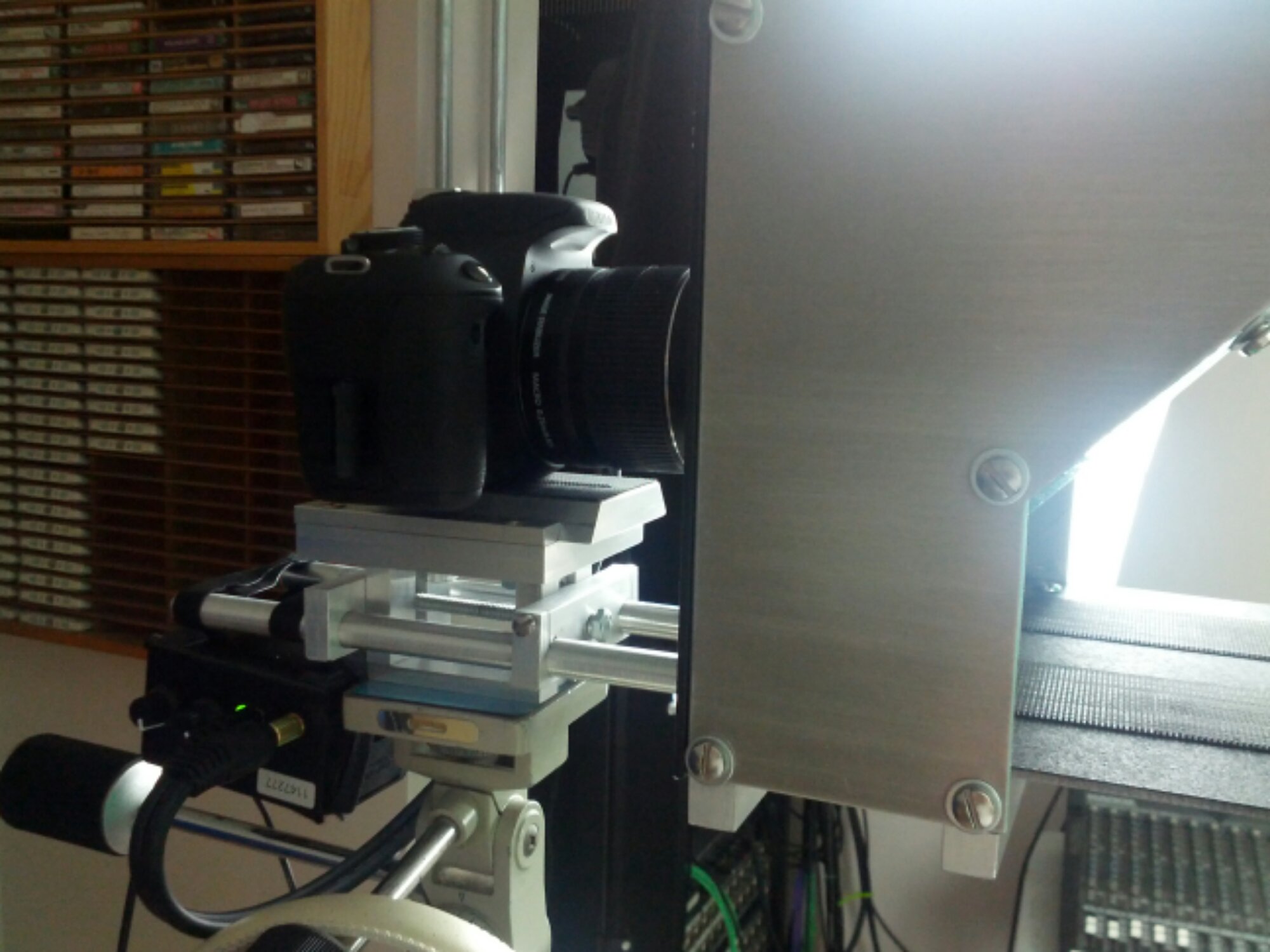
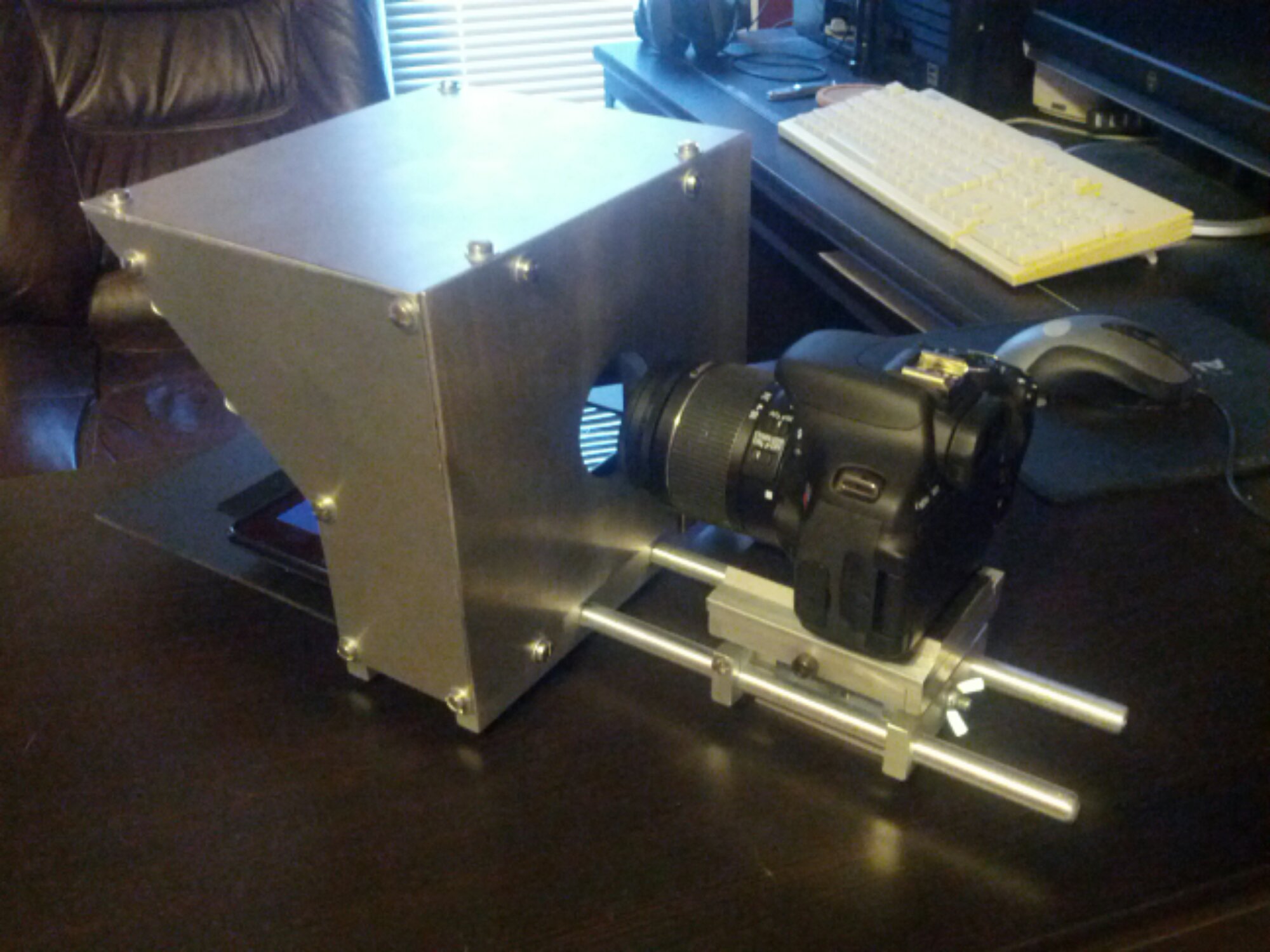
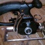
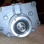
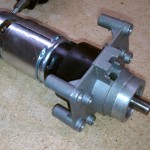
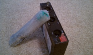
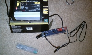
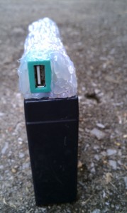
Here’s a couple pictures from my last project: tablet-based teleprompter with 15mm support rods and a quick disconnect camera system. It turned out very well. One of these days I’ll post up some more detail.
But that project’s over and my shop is missing me. This time I’m getting back to electronics. Lately I’ve been playing the old NES games. Well, when I say playing, I mean with my original NES. I left a cartridge in the console the last time I played it and all of the pins got stressed, resulting in the blinking display. This is typical when the pins connecting to the cartridge don’t make a good connection. Bending them back was an easy fix, and didn’t even require the removal of the security chip.
Anyways, now I’m trying to make a portable system based on a Raspberry Pi. Having installed the RetroPie distribution, running NES/SNES/Genesis/etc. emulators are a breeze. I bought a few other components to make sure everything would work, and then started designing.
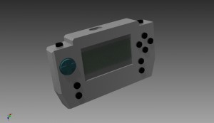
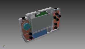
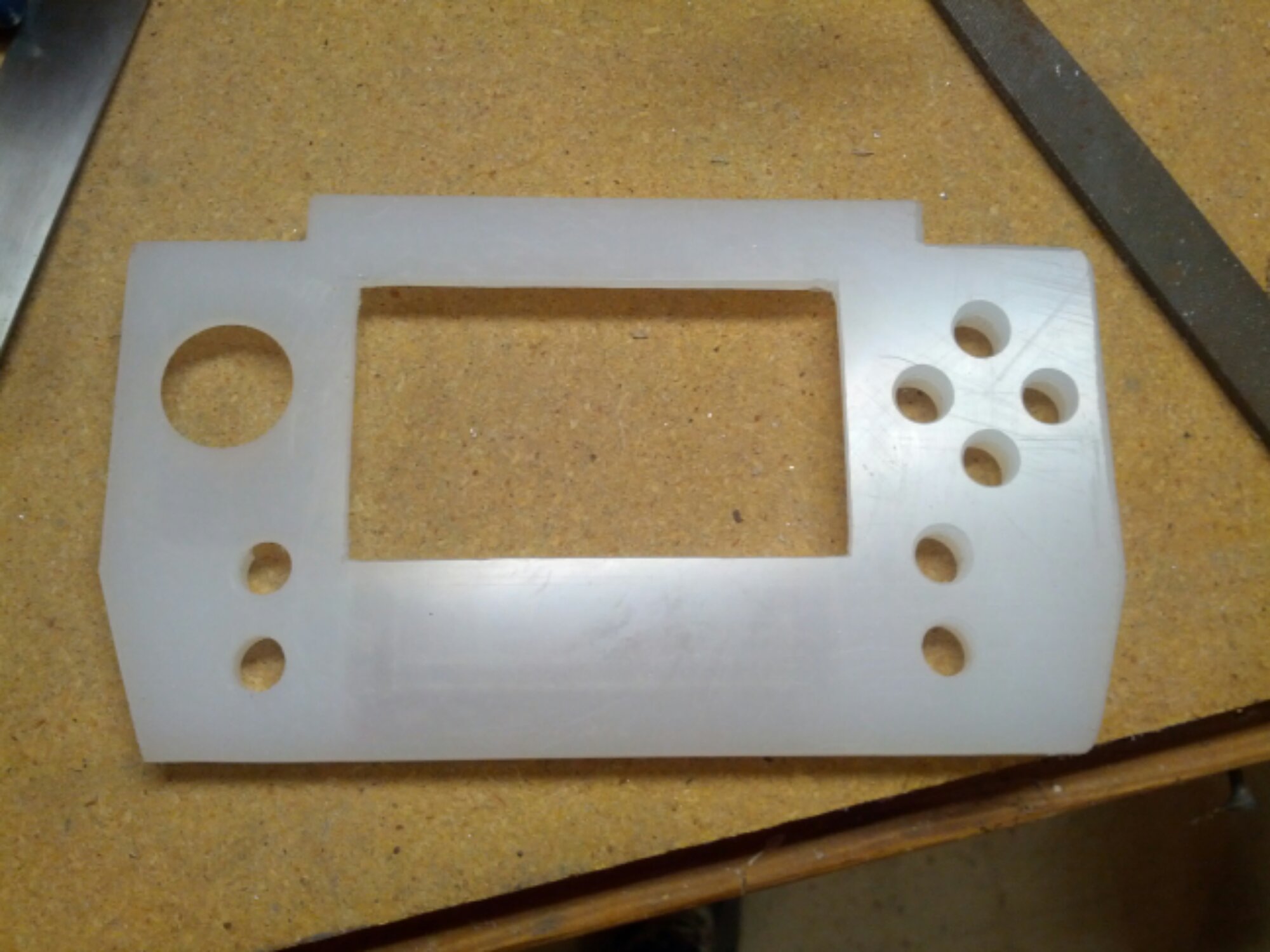
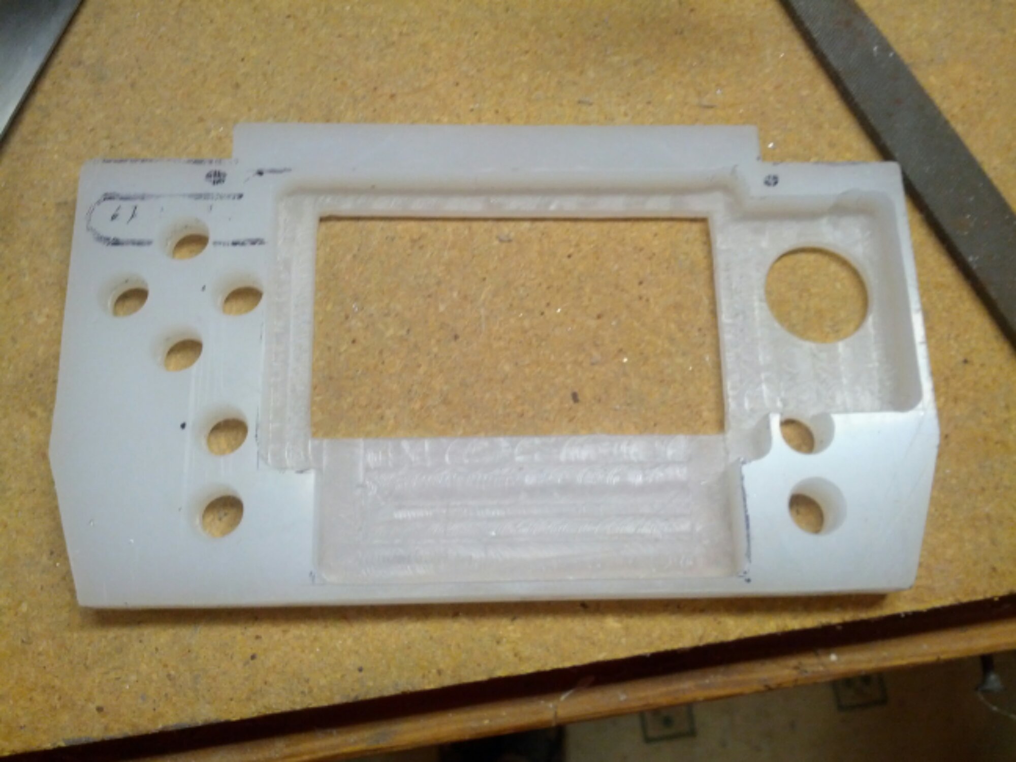
Here’s what I’ve come up with. I went through several revisions, trying to maximize space and portability. At the same time, I tried to keep ergonomics in mind. The size is a bit chunky, but feels good in the hand so far. The enclosure is made of two pieces of polypropylene. Originally I wanted it all milled out of solid aluminum. Not wanting to spend 500 hrs making billions of passes milling, I chickened out for something much easier to machine (set RPMs low and make heavy cuts).
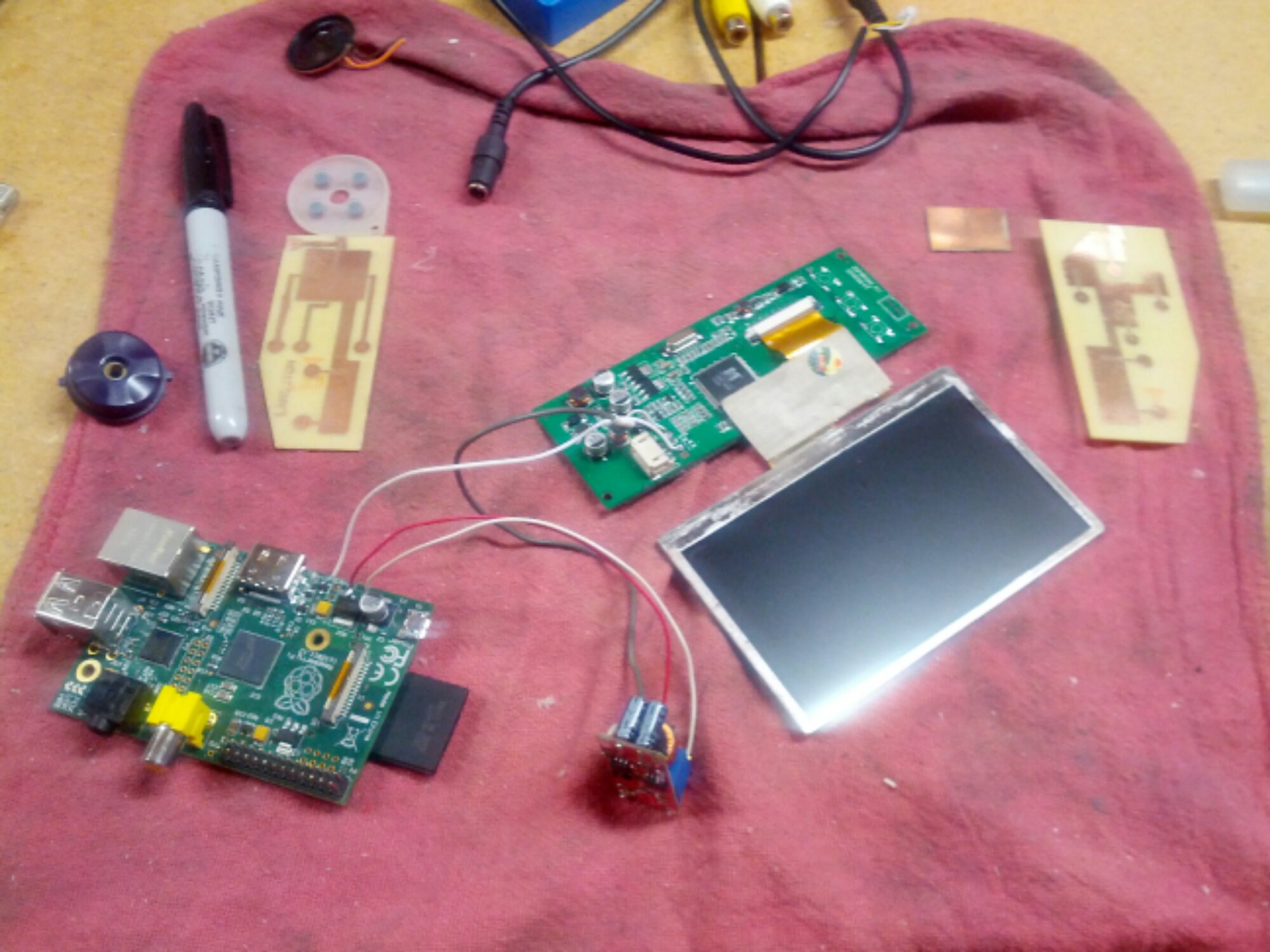
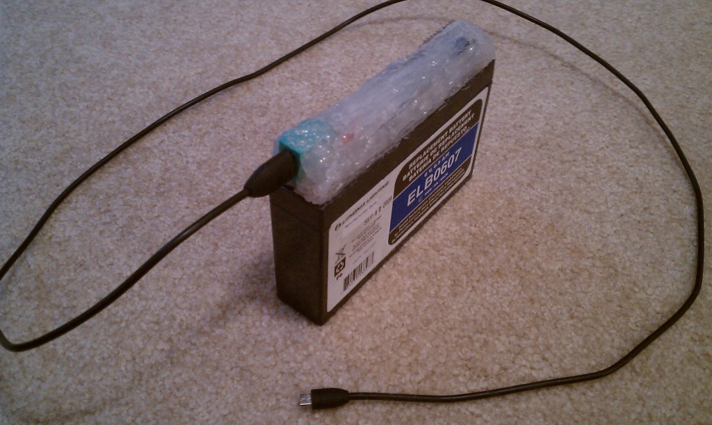
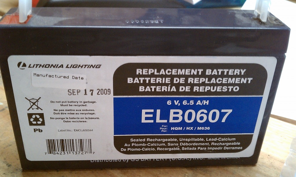
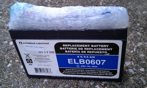
The parts I’m using are, mostly, shown below: a Raspberry Pi, a 12V-5V switching regulator from eBay, a 4.3″ TFT car monitor from Amazon, a 12V LiPo battery with integrated charging and power switch components from eBay, and the little silicon pads from a Logitech Gravis Gamepad Pro that doesn’t work. Oh, and a Teensy v3 to make the gamepad portion.
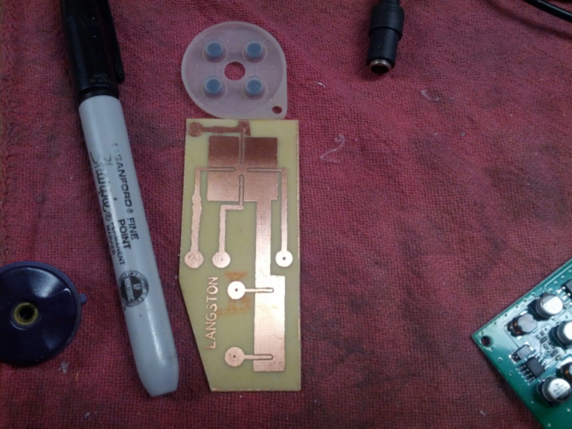
Since I’m splitting up the buttons from a traditional gamepad with the monitor in the middle, I needed some custom PCBs. Gamepads work by closing circuits to ground via silicon pads with bits of carbon in it. I could use some pushbuttons, but wanted to retain the nice action of a gamepad button. Once I got the dimensions and button positions from Inventor, I made the PCB layout in DipTrace. Then I used the tried and true laser toner, copper clad PC board, and ferric chloride PCB solution. It took a few tries, but I like the results.
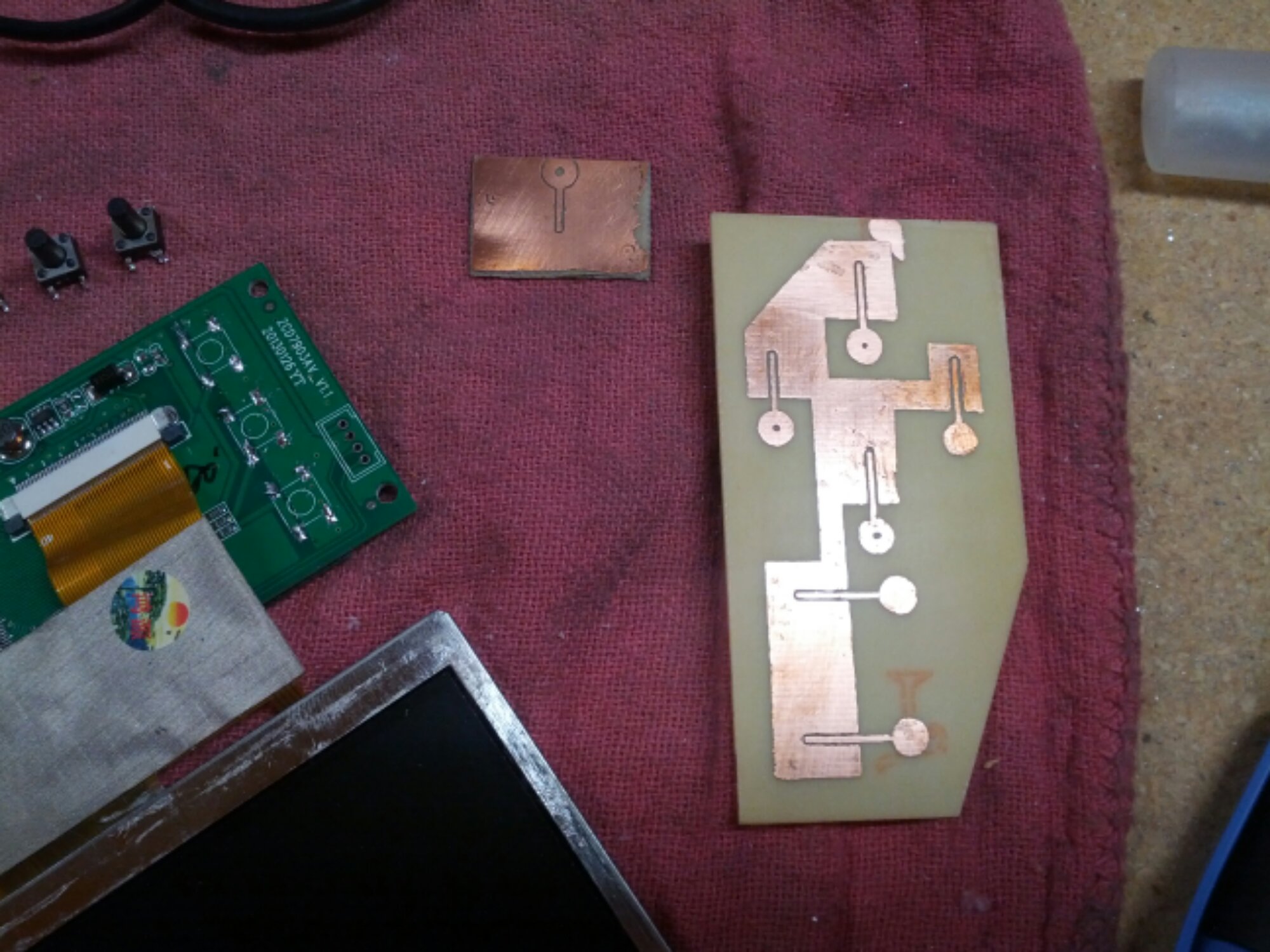
The 4.3″ TFT monitor is a great deal for $18. I just need to make some changes to get it how I wanted. First was to remove the case and hardwire the power to the battery and to the regulator. Next I needed to remove the pushbuttons on the back of the monitor. Eventually I’d like to control them via my Teensy microcontroller because they bring up the menu for setting things like brightness, etc.
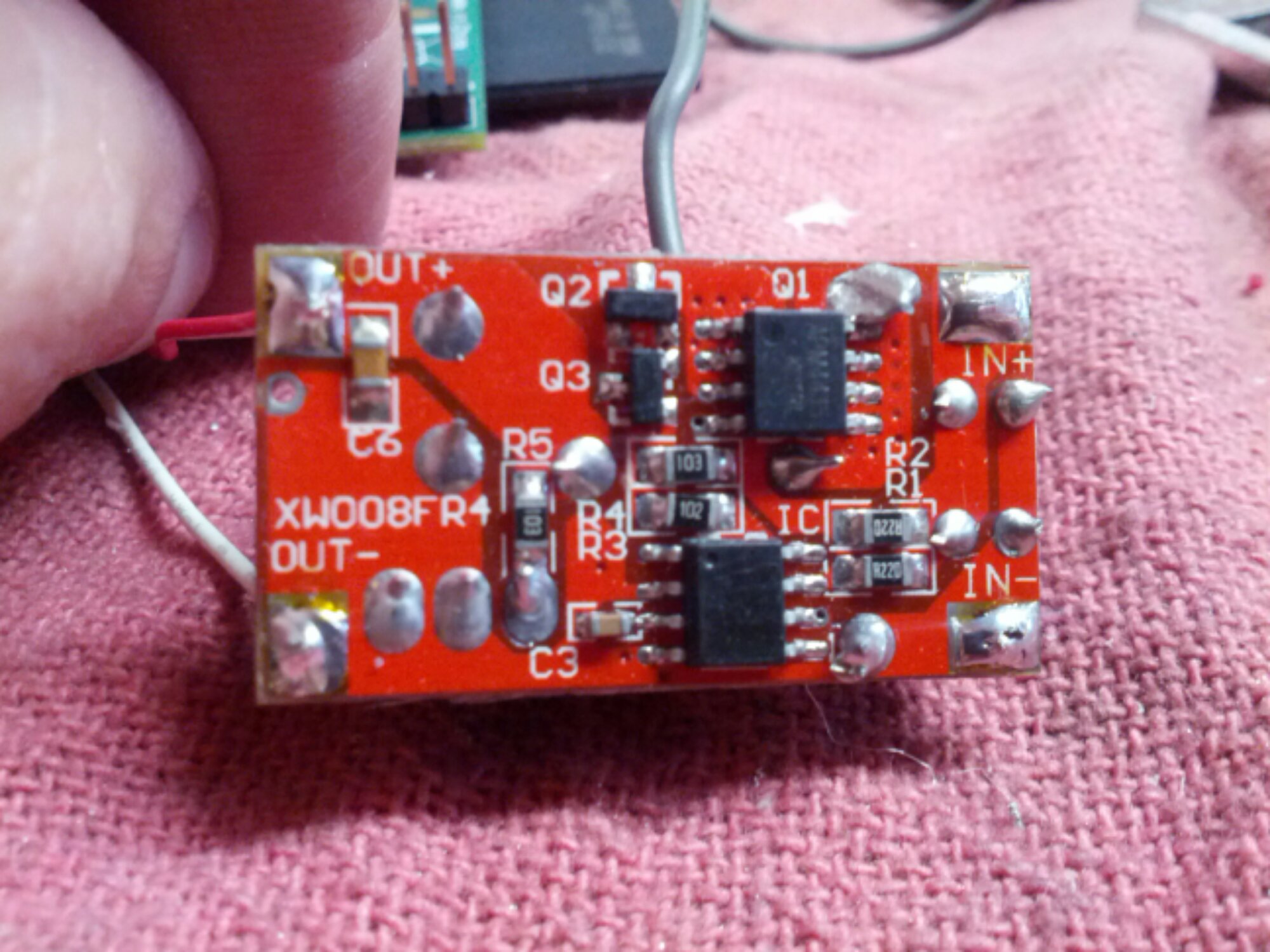
When I first got the regulator I was a bit suspicious since it looked like there was a big glob of solder bridging a couple nodes. Metering it all out it appears OK.
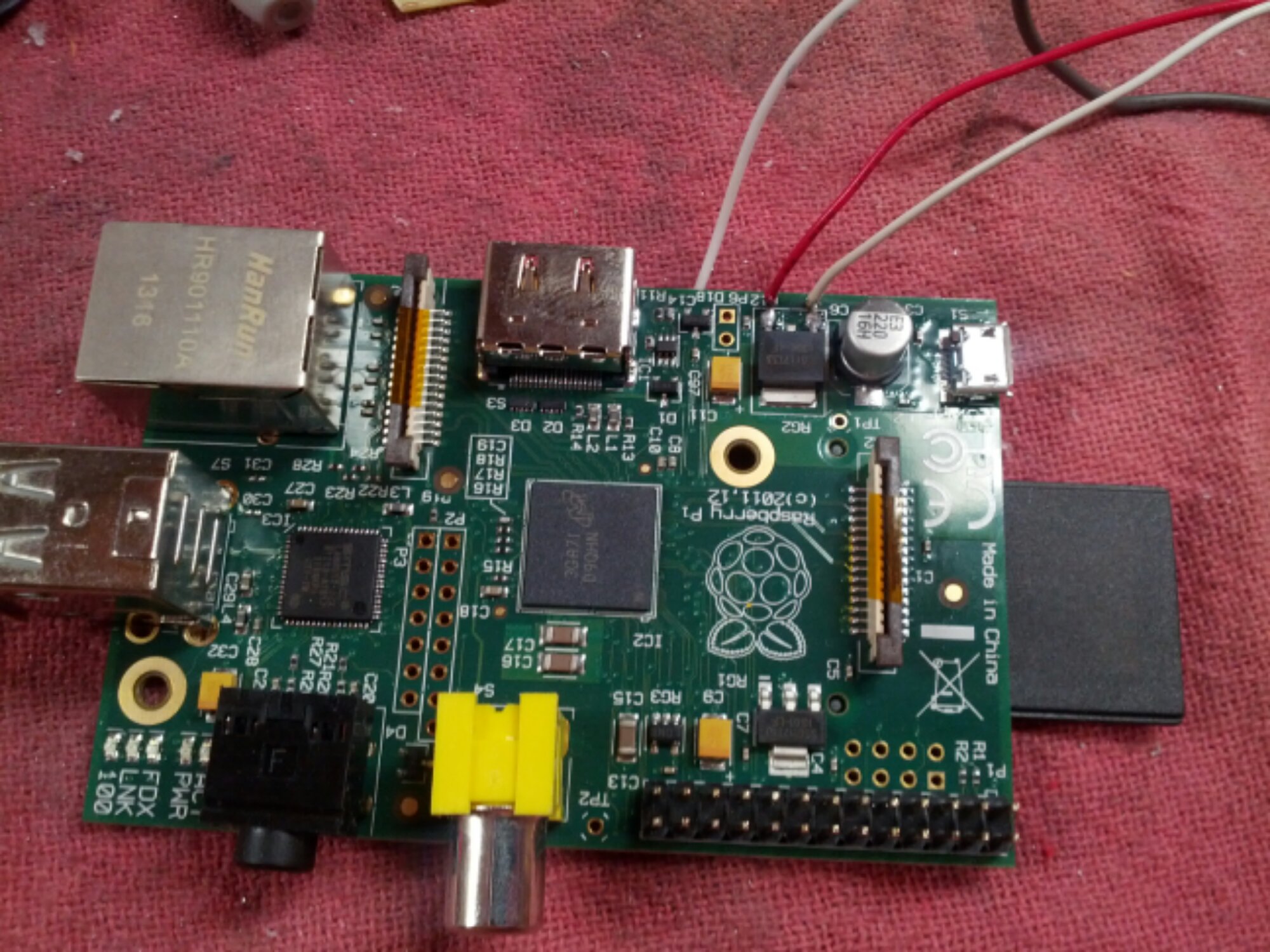
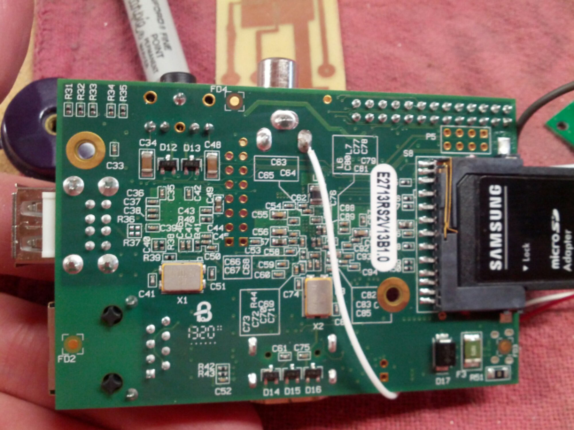
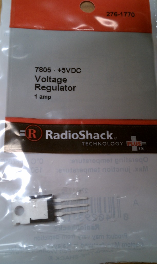
I then hardwired power and NTSC video directly to the Raspberry Pi. The main regulator pads were the best place to supply 5V and bypass the USB port.
Lastly I started fabricating the front of the enclosure. I’ve got about 8 hrs into it now and haven’t made any mistakes – yay! Unfortunately I ran out of polypropylene and had to put in a new order. In the meantime, I am going to make the buttons. Well, that’s all for now…
