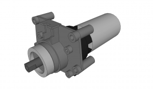
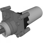
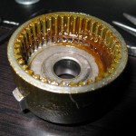
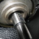
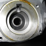
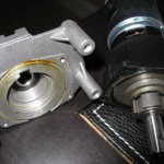
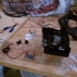
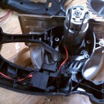
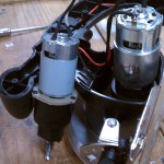
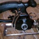
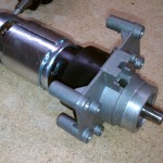
I spent some time the other day modeling the HF 18V Circular Saw motor and bracket. Since I don’t have the money for pro CAD programs, I use Google Sketchup. Great product for free, and it’s very simple to use. The most time I spend modeling is just using the calipers, rechecking, and then checking again. I’ve posted the sketch to the Sketchup Warehouse.
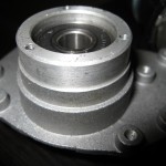
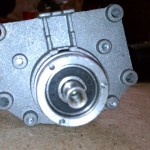
While modeling it, I’ve been thinking about how to mount it. There aren’t any easy flat faces and the cast aluminum is only about 0.1″ thick. Several options are available. I could mill the front face flush and machine an aluminum mounting plate for it to mount to. This isn’t my preferred choice because it could easily break and I’d be hosed. Another option is to make a similar mounting plate without milling the current bracket. That’s the easiest way out, and I haven’t completely decided against it. The four deep holes on the corners could be threaded or just put a bolt and nut to it. Since there isn’t a lot of material there, helicoils wouldn’t be an option, but there’s a full inch to bite onto so…I don’t know yet.
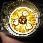
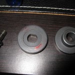
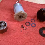
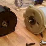
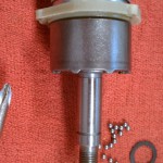
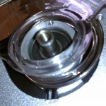
Another option is to make a custom bracket that would mate directly with the black plastic gear casing. The longer I look at it, the easier it looks to do. Here’s a closer look at what is actually inside.
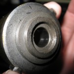
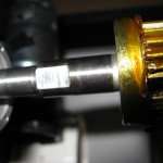
As you can see, the current bracket houses a 6000RS series ball bearing. I’m sure it’s there to stay, so I’d have to buy another if I remade it. Over the next few days I will update my model to show these parts. If you were wondering what the oddly shaped part was that rides on the shaft, it’s a locking mechanism for holding the shaft when you are changing blades on the saw. Here’s the product manual showing an exploded parts list.
Edit:
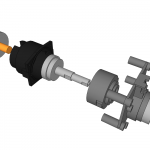
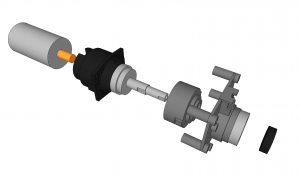
I’ve redrawn the motor, bracket, and other inside goodness, and posted it to the Sketchup Warehouse. The planetary gears aren’t drawn because I’m lazy. Here’s an exploded view:
