Jeremy W. Langston

Personal Website

Page 2 of 4

SAWBOT? QUE?!

Having no money after buying tools and tooling, I’ve had plenty of time to plan out a robot platform.  There are several ideas rolling around in my head.  They range from independently-driven, independently-suspension-ed (?) 4WD drivetrains, to Ackerman-steering platforms with front, rear, and center differentials.  Yeah, overly complex, at least for now.  I’m instead going for a simple skid-steer drivetrain with no suspension other than the tires.  The left-side two wheels will be driven by one motor, as is the right side.  The difference in speeds causes the platform to turn.  I also want to be able to get this thing up to a pretty good speed so I can run around with it like an RC car:  ~20mph.  I can already see it busted on a wall.  It’s going to be great.

Now the question is where can I find motors?  Ideally the shaft speed of the motor would be the same as the wheel speed.  I found that to be impossible within a reasonable budget (<$50 ea).  Typically the motors you find on RC trucks run at about 4,000 kv.  For those that don’t know, a 4,000 kv motor runs at 4,000 rpm PER VOLT.  Don’t get me wrong.  A robot rolling down the road at 476mph would be cool.  Maybe later.  So, I’ll need to go with a gear reduction.  It turns out that it can get expensive.  Making a custom gearbox is an option.  However it takes some careful design work to ensure proper meshing.  I don’t think my master metalworking skills are quite up to that just yet.

I came across several people repurposing a cordless drill motor.  Now there’s an idea!  At Harbor Freight, you can get cheap Chinese junk like cordless drills.  The batteries are horrible and the clutch be worn out fast.  However, the motor and gearbox are pretty decent – and the output shaft speed is around 500 RPM, unloaded.  Not bad for $20.  I picked up a couple.

IMAG0178 IMAG0145 IMAG0183

Bringing back the drills, I torn one apart and looked to see how I would mount it.  The plastic housing and extended shaft would take up too much space in my robot. The plastic housing is part of the clutch assembly, as it allows the ring gear to spin if the clutch isn’t tightened all the way (the drill setting).  Also, proper mounting is non-trivial.  I came across another site showing a custom gearbox enclosure for a drill.  This is definitely the way to go as it gives you a better fit and mounting options.

Then I came across this:

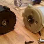
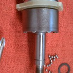
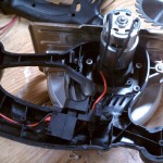
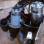
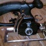
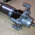
It’s the Harbor Freight 18V 5-1/2″ Cordless Circular Saw, part # 67026, and was on sale for $25.  The no-load speed is 3800 RPM, uses a larger 750-sized motor, and has a mounting bracket already!  As far as I know, no one else has tried this.  That’s usually a bad sign, but it’s worth a shot.

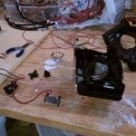
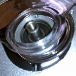
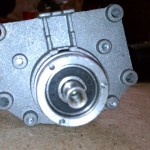
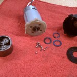
Here are some pictures from the break-down process.

Random Youtube video of the motor?  Sure, here you go: http://www.youtube.com/watch?v=3KQaba3A2qI
Glacern GSV-440

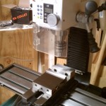
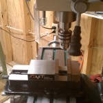
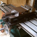
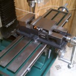
My new vise came in the mail today!  It’s a Glacern GSV-440 4″ Vise.  A vise is not one of those things things I wanted to skimp on, as I’ve seen the Chinese junk.  Sure you can still make good stuff with one of the junkers.  However,  I don’t want to spend a lot of time just getting my vise to function as a vise.  At $224, the GSV-440 isn’t cheap, but it’s a whole lot less than similarly sized Kurt’s.  I went with the 4″ thinking that the 5″ and 6″ would be too large for the G0704 – and I think the 4″ is a perfect fit.

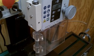
Removing the safety guard on the Grizzly G0704 Mill

I’ve only used  my mill briefly and already noticed that the safety guard on my G0704 mill just had to go.  Basically it works by pressing a switch when the guard is flipped out, causing the mill to stop.  Good idea, but the plastic guard gets in the way.  So, here’s the easiest way of removing the guard without having to splice anything.

IMAG0082

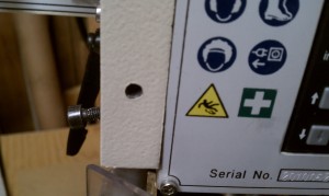
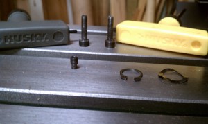
Step 1) Remove the snap ring on the top of the guard.

IMAG0083

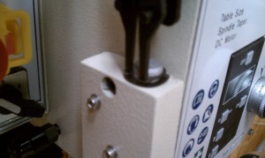
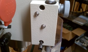
Step 2) Remove the two hex bolts holding the switch housing to the head.

IMAG0091

Step 3)  Take out the set screw holding the guard to the switch housing.  Careful – nothing is really holding the guard up.

IMAG0098

IMAG0104

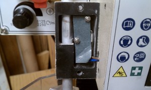
Here you can see how it actually works.  Behind the paper strip is a micro-switch.  When the guard is flipped out, the switch presses in.

IMAG0099

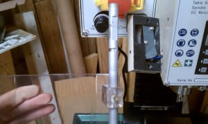
Step 4)  Flip the guard open and pull straight down until it comes out.  Finally bolt the switch housing back onto the head and you’re done.

IMAG0102

Steps for using MATLAB C/C++ Compiler with Visual C++

In Visual Studio:

0)  Create an empty C/C++ project.

 
In MATLAB:

1)  Write the m-file with one function to expose to C/C++.

        function [xp, length] = ExpandArray( x, interval)
        xp = 0:interval:x(length(x));
        length = length(xp);

2)  Create a deployment project (File->New->Deployment Project).

3)  Add m-file to “Exported functions” in deployment project.

4)  Change the settings of the deployment project to put the output directory output to the directory of the source files for the C/C++ project.  Set the Library Name (e.g. “Functions”).
In Visual Studio:

5)  Right-click on the project->Properties.

5a) Under C/C++->General, add the directory of the MATLAB header files to “Additional Include Directories”:

      "C:\Program Files\MATLAB\R2007a\extern\include"

5b) Under Linker->Input, add the directory of the MATLAB libraries and the location of your newly created MATLAB library to “Additional Dependencies”:

      "C:\Program Files\MATLAB\R2007a\extern\lib\win32\microsoft\mclmcrrt.lib"
      "C:\...\Functions.lib", where "..." is the path of the output directory set in step 4

6)  Add the created header file to your project and include it in your C/C++ code where appropriate.

7)  In your C/C++ code, initialize the MATLAB component:

      bool ret = FunctionsInitialize();
      if (!ret){
        std::cout << "Error initializing MATLAB Component Runtime\n";
        system("PAUSE");
        return 0;
      }

8)  Create the input variables to the MATLAB function:

      double x[4] = {1,2,3,4};
      mwArray mwX(1,4,mxDOUBLE_CLASS);
      mwX.SetData(x,4);
      mwArray mwInterval((double) 0.1);
      int nargout = 2; // this says you will be using 2 outputs, xp and length

9)  Create the output variables from the MATLAB function:

      mwArray mwXP;
      mwArray mwLength;

10) Call your function:

      ExpandArray(nargout, mwXP, mwLength, mwX, mwInterval);

11) Get the data out of the mwArrays:

      int length;
      mwLength.GetData(&length, 1);
      double *xp = new double[length];
      mwXP.GetData(xp, length);

12) Terminate the use of the MATLAB component:

      FunctionsTerminate();

 
Notes:

If you only want to return one variable from your MATLAB function, set
nargout to 1 and the return variable will be as such:
  int returnVariable = MyFunction(nargout, inputVariable);

Battery-powered USB Phone Charger

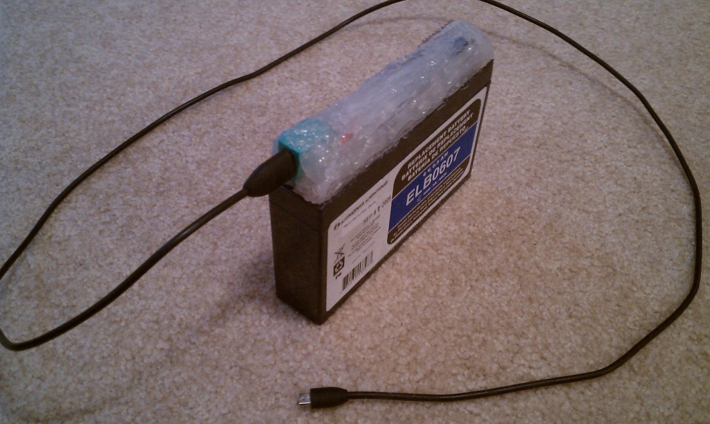
I was getting ready for a long train ride from KY to DC and found out there aren’t any AC outlets for coach seats!  A 15hr ride isn’t too bad when you have a smart-phone; then again, the stock battery on an HTC Incredible will last only about 3hrs of heavy usage.  Not good.  I wanted a way to be able to use it for, well, 15hrs.  So, using some easy-to-find parts I made an extended battery that will charge the phone via USB.  I also wanted the extended battery to be rechargeable.  So, I need to be able to have access to the battery contacts; maybe later I will add something fancier, but for now the battery disconnects from the USB circuitry.  Here’s my finished product, and how to make it.

IMAG0075

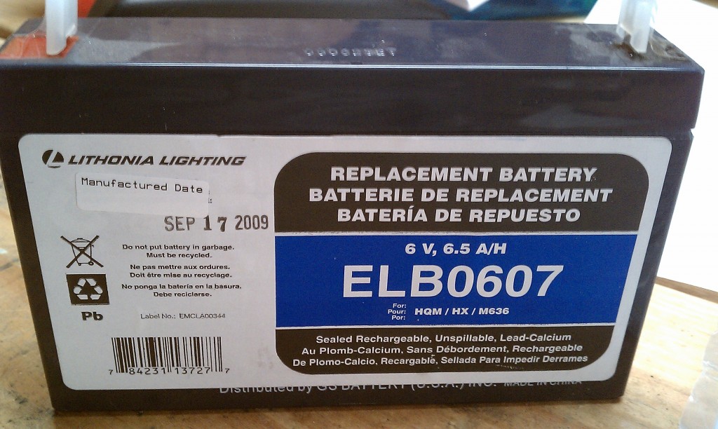
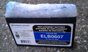
I bought a battery from the local Home Depot for $20 (look in the outdoor lighting aisle).  It is 6V and provides 6.5AH.  You can get it cheaper at places like batterymart.com, but I was in a hurry and the shipping on seal-lead acid batteries is not cheap.  The higher the amp-hours (6.5AH in this case), the longer you will be able to run your USB device.

IMAG0064

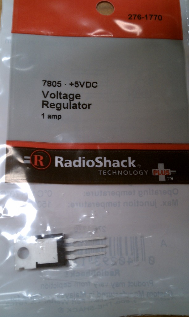
Now for the voltage – USB uses 5V DC.  I needed to drop the voltage from 6V to 5V, preferably without too much loss.  There are three main options:  voltage divider using resistors, non-switching regulator, and a switching regulator.  In the case of the voltage divider, the resistors basically turn the extra voltage into heat, and they would need to be rated for higher power than the typical $0.01 resistors.  Switching regulators, or DC-to-DC converters, are much higher efficiency, but are more costly.  Also, I couldn’t find one that would work at Radio Shack, so I went with a non-switching regulator:  the 7805.

IMAG0066

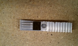
The 7805 regulator will take voltages higher than 5V and hold them at 5V, also allowing up to 1A of current.  While that’s much more than is needed, it gives a nice buffer.  A regulator has three legs:  1) input, 2) ground,  and 3) output, where the ground leg is shared between the input and output.  The input comes from the positive side of the battery, the output goes to the 5V pin on a USB connector, and the negative side of the battery along with the GND pin on a USB connector both connect to the ground.  Since the 7805 drops the difference in voltage by heat, adding a heatsink to the regulator might be needed, depending on how much power your device will draw.

IMAG0063IMAG0068

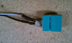
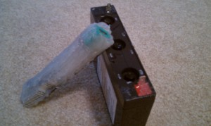
To connect USB devices, I need an adapter that would allow me to plug in a standard USB cable, like the one in your computer.  I happened to have an old PS2/USB adapter from an old mouse.  It hasn’t been used, ever, so I cut it up (the green thing above).  You could use something else, like a USB extension cable which already has wires to solder to.  USB connectors have 4 pins:  1) 5V, 2) Data+, 3) Data-, and 4) GND.  Use some wire to solder the connections (USB 5V -> 7805 Output), (USB GND  and Battery negative -> 7805 Ground), and (Battery positive -> 7805 Input).  Make sure to protect the solder points with some heatshrink or risk shorting, melting, and other bad things.  To connect the wires to the battery terminals, I used spade connectors.  Also, leave the terminals pointing up for reasons I’ll point out soon.

IMAG0067IMAG0069

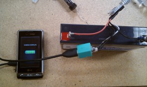
Once the soldering is done, connect the battery and use a multimeter to check the output on the USB connector (voltage across pin 1 and pin 4 should be +5VDC).  Then you can freely connect a USB device and you’re set.  You could stop here and be done.  Since I wanted this for travel and didn’t want exposed wires, I took it a step further:  enter hot glue.

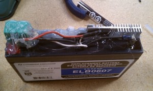
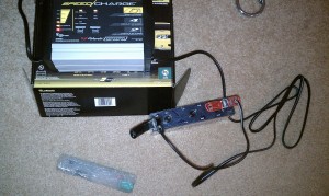
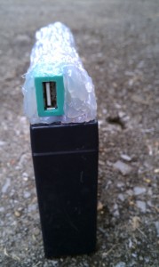
Clean the top of the battery and add a layer of lubricant (e.g. WD-40) to keep the glue from sticking to the battery.  We want the circuitry to be detachable so that we can recharge the 6V battery using a trickle charger/car charger.  This is why I left the battery terminals sticking up – so that I can freely pull the circuit away from the battery.  I used about 10 – 15 sticks of hot glue used on a mini gun, just to make sure that everything would hold together.  This is the most time-consuming part.  It doesn’t take a lot of thought to do this.  Just fill in all the holes, keeping the USB port accessible.  You also want to keep the heatsink partially uncovered so that it passing air can pull away the heat given off by the 7805 regulator.  You could spend a lot of time getting this pretty by squaring up the sides and making it colored, but this was a last minute project for me.  Hopefully you will get some good use out of this – I know I will.  I hope they don’t kick me off the train thinking it’s a bomb.

IMAG0070IMAG0072

IMAG0077IMAG0078

IMAG0073

« Older posts Newer posts »

© 2024 Jeremy W. Langston

Theme by Anders NorenUp ↑